Manufacturing tolerances: standard vs precision
SSG MFG engineering7 min readCNC machining
What tolerances can manufacturing processes hold?
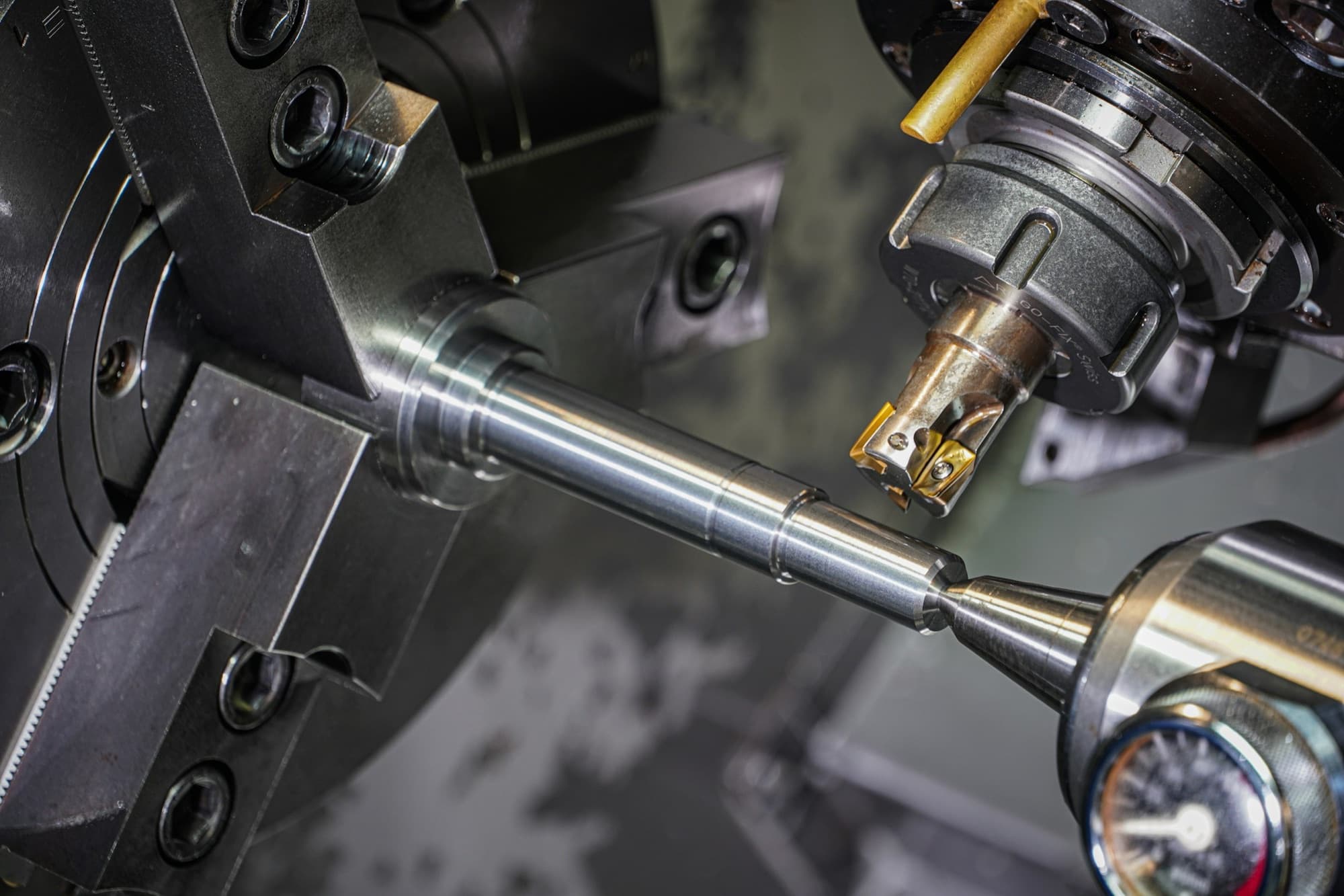
Standard CNC machining holds ±0.005 in (±0.13 mm) without special effort and ±0.001 in (±0.025 mm) with care. Injection molding typically holds ±0.003–0.005 in on small features, aluminum die casting about ±0.010 in on the first inch, and stamping ±0.005 in. Tighter tolerances cost more at every step, so apply them only to features that affect fit or function.


What is a standard tolerance?
A standard tolerance is what a process holds at normal speeds with normal inspection. On a drawing, the title block sets a general tolerance for every dimension without its own callout, such as .XX ±0.010 in and .XXX ±0.005 in, or a note like ISO 2768-m. Because the title block covers most dimensions, it drives more cost than any single callout.
What tolerances can each process hold?
| Process | Standard | Precision | Notes |
|---|---|---|---|
| CNC milling | ±0.005 in (±0.13 mm) | ±0.001 in (±0.025 mm) | ±0.0002–0.0005 in with grinding |
| CNC turning and screw machining | ±0.002–0.005 in (±0.05–0.13 mm) | ±0.0005 in (±0.013 mm) | Diameters hold tighter than lengths |
| Injection molding | ±0.003–0.005 in (±0.08–0.13 mm) on the first inch | ±0.001–0.002 in (±0.025–0.05 mm) | Add roughly 0.001–0.002 in per additional inch; resin shrinkage drives it |
| Aluminum die casting | ±0.010 in (±0.25 mm) first inch, plus ±0.001 in per additional inch (NADCA standard) | NADCA precision values or machining | Add allowance across the parting line and moving slides |
| Progressive-die stamping | ±0.005 in (±0.13 mm) | ±0.001–0.002 in hole to hole | Formed features looser; bend angles ±1° |
| Sheet metal fabrication | ±0.005 in cut; ±0.010 in formed | ±0.005 in formed | Tolerance accumulates across each bend |
| Powdered metal | ±0.001–0.002 in per inch radial, as sintered | ±0.0005 in with sizing | Height (press direction) typically ±0.003–0.005 in |
| Closed-die forging | ±0.015–0.030 in (±0.4–0.8 mm) | ±0.005–0.010 in precision forging | Plus mismatch and flash allowances |
| Investment casting | ±0.005 in per inch | ±0.003 in per inch | Larger features loosen proportionally |
| Rubber extrusion | ARPM class E3 (commercial) | ARPM class E1 (high precision) | Cross-section tolerance grows with size |
| 3D printing (SLS, MJF) | ±0.010 in or ±0.3% | ±0.005 in on small features | Varies by machine and orientation |
What is ISO 2768?
ISO 2768-1 sets general tolerances for linear and angular dimensions that have no individual tolerance, in four classes: f (fine), m (medium), c (coarse), and v (very coarse). A note such as ISO 2768-mK adds class K geometric tolerances from ISO 2768-2. ISO 22081 is the newer standard for general geometrical specifications, but ISO 2768 notes remain common.
| Nominal size | f (fine) | m (medium) | c (coarse) | v (very coarse) |
|---|---|---|---|---|
| 0.5–3 mm (0.02–0.12 in) | ±0.05 mm (±0.002 in) | ±0.1 mm (±0.004 in) | ±0.2 mm (±0.008 in) | Not specified |
| Over 3–6 mm (0.12–0.24 in) | ±0.05 mm (±0.002 in) | ±0.1 mm (±0.004 in) | ±0.3 mm (±0.012 in) | ±0.5 mm (±0.020 in) |
| Over 6–30 mm (0.24–1.18 in) | ±0.1 mm (±0.004 in) | ±0.2 mm (±0.008 in) | ±0.5 mm (±0.020 in) | ±1.0 mm (±0.039 in) |
| Over 30–120 mm (1.18–4.72 in) | ±0.15 mm (±0.006 in) | ±0.3 mm (±0.012 in) | ±0.8 mm (±0.031 in) | ±1.5 mm (±0.059 in) |
| Over 120–400 mm (4.72–15.7 in) | ±0.2 mm (±0.008 in) | ±0.5 mm (±0.020 in) | ±1.2 mm (±0.047 in) | ±2.5 mm (±0.098 in) |
| Over 400–1000 mm (15.7–39.4 in) | ±0.3 mm (±0.012 in) | ±0.8 mm (±0.031 in) | ±2.0 mm (±0.079 in) | ±4.0 mm (±0.157 in) |
| Over 1000–2000 mm (39.4–78.7 in) | ±0.5 mm (±0.020 in) | ±1.2 mm (±0.047 in) | ±3.0 mm (±0.118 in) | ±6.0 mm (±0.236 in) |
| Over 2000–4000 mm (78.7–157 in) | Not specified | ±2.0 mm (±0.079 in) | ±4.0 mm (±0.157 in) | ±8.0 mm (±0.315 in) |
Class m is the usual default for machined parts, f for precision machined parts, and c or v for fabrications and weldments. For classes f and m, angular deviations run from ±1° on short legs up to 10 mm down to ±0°5′ on legs over 400 mm. Molded and cast parts usually reference their own standards instead: ISO 20457 for molded plastics, ISO 8062 for castings, and NADCA standards for die castings.
How much do tight tolerances cost?
Cost rises faster than the tolerance shrinks. Tighter features need slower feeds, extra finishing passes, temperature control, grinding or honing, more inspection time, and more scrap. The table below is a rule of thumb for a single feature on a small machined part.
| Tolerance | Typical method | Relative cost |
|---|---|---|
| ±0.010 in (±0.25 mm) | Standard machining, minimal inspection | About 1.0× |
| ±0.005 in (±0.13 mm) | Standard machining | About 1.0–1.1× |
| ±0.002 in (±0.05 mm) | Finish passes, in-process gauging | About 1.3–1.6× |
| ±0.001 in (±0.025 mm) | Slow finishing, temperature-stable shop, CMM inspection | About 1.5–2.5× |
| ±0.0005 in (±0.013 mm) | Grinding, honing, or lapping | About 2–4× |
| ±0.0002 in (±0.005 mm) | Precision grinding or lapping in a controlled environment | 4× or more |
- Measurement: the gauge should resolve about one tenth of the tolerance, and gauge R&R should stay under 10% of it.
- Molded and cast parts: tolerances tighter than the process standard mean tool iterations or a secondary machining step.
- Scrap and sorting: parts near the limit get rejected, and the price absorbs the yield loss.
What are the basics of GD&T?
Geometric dimensioning and tolerancing (GD&T) controls form, orientation, location, profile, and runout relative to datums. In the US it is defined by ASME Y14.5-2018; internationally by ISO 1101 and related ISO GPS standards. It tells the inspector how to fixture and measure the part, and it often allows more manufacturing tolerance than ± coordinate dimensions for the same function.
| Category | Characteristics | Controls |
|---|---|---|
| Form | Flatness, straightness, circularity, cylindricity | Shape of a single feature; no datum |
| Orientation | Parallelism, perpendicularity, angularity | Tilt relative to a datum |
| Location | Position (concentricity and symmetry were removed in the 2018 edition) | Where a feature sits relative to datums |
| Profile | Profile of a line, profile of a surface | Shape, size, and location of complex surfaces |
| Runout | Circular runout, total runout | Wobble of a surface rotated about a datum axis |
- Datums: the primary, secondary, and tertiary references (A, B, C) that the part is fixtured against, ideally matching how it mounts in the assembly.
- Feature control frame: the box that states the characteristic, tolerance value, modifiers, and datums.
- Basic dimensions: boxed, theoretically exact dimensions that locate a tolerance zone.
- MMC and LMC modifiers: they add bonus tolerance as a feature departs from its maximum or least material condition.
How do tolerances stack up in an assembly?
A stack-up adds the tolerances along a chain of dimensions to find the worst variation at a gap or fit. Worst-case analysis adds them directly. Root sum square (RSS) analysis assumes independent, centered, normally distributed processes and takes the square root of the sum of squares.
Four parts at ±0.005 in each stack to ±0.020 in worst case and about ±0.010 in by RSS. Use worst case for safety-critical fits and low volumes. RSS is reasonable at production volume, but only if the processes are capable and centered.
How should you specify tolerances on a drawing?
- Set a realistic general tolerance in the title block, such as ISO 2768-m or ±0.010 in on two-place decimals.
- Put tight tolerances only on features that affect fit, sealing, motion, or safety.
- Use GD&T for relationships between features, with datums that match how the part assembles.
- Dimension from datums rather than chaining dimensions, which accumulates tolerance.
- Match each tolerance to the process, or show the feature as machined after casting, molding, or forming.
- Specify surface finish only where it matters: Ra 125 µin (3.2 µm) is standard machined, 63 µin (1.6 µm) fine, 32 µin (0.8 µm) ground.
- Flag critical characteristics so the supplier builds them into the control plan.
How do you get a tolerance review through SSG?
Upload the STEP file and drawing to the builder at /build for an instant budgetary estimate and DFM feedback, and use it to catch features that are tighter than the process needs. For firm quotes, an SSG rep routes the RFQ to principals whose equipment and inspection hold the tolerances that matter. Independent reps can join the network at /network and submit jobs for their customers.